Use case diagram is a behavioral UML diagram type and frequently used to analyze various systems. They enable you to visualize the different types of roles in a system and how those roles interact with the system. This use case diagram tutorial will cover the following topics and help you create use cases better.
A UML (Unified Modeling Language) use case diagram is a visual representation of the interactions between actors (users or external systems) and a system under consideration. It depicts the functionality or behavior of a system from the user’s perspective. Use case diagrams capture the functional requirements of a system and help to identify how different actors interact with the system to achieve specific goals or tasks.
Use case diagrams provide a high-level overview of the system’s functionality, showing the different features or capabilities it offers and how users or external systems interact with it. They serve as a communication tool between stakeholders, helping to clarify and validate requirements, identify system boundaries, and support the development and testing processes.
As mentioned before use case diagrams are used to gather a usage requirement of a system. Depending on your requirement you can use that data in different ways. Below are few ways to use them.
Use case diagrams consist of 4 objects.
The objects are further explained below.
| Symbol | Name | Description |
|---|---|---|
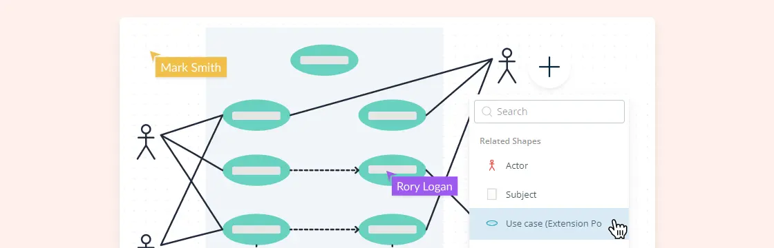
 | Actor | Actor in a use case diagram is any entity that performs a role in one given system. This could be a person, organization or an external system and usually drawn like skeleton shown below. |
 | Use Case | A use case represents a function or an action within the system. It’s drawn as an oval and named with the function. |
 | System | The system is used to define the scope of the use case and drawn as a rectangle. This an optional element but useful when you’re visualizing large systems. For example, you can create all the use cases and then use the system object to define the scope covered by your project. Or you can even use it to show the different areas covered in different releases. |
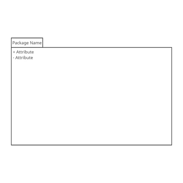 | Package | The package is another optional element that is extremely useful in complex diagrams. Similar to class diagrams, packages are used to group together use cases. They are drawn like the image shown below. |
Although use case diagrams can be used for various purposes there are some common guidelines you need to follow when drawing use cases.
These include naming standards, directions of arrows, the placing of use cases, usage of system boxes and also proper usage of relationships.
We’ve covered these guidelines in detail in a separate blog post. So go ahead and check out use case diagram guidelines.
There are five types of relationships in a use case diagram. They are
We have covered all these relationships in a separate blog post that has examples with images. We will not go into detail in this post but you can check out relationships in use case diagrams.
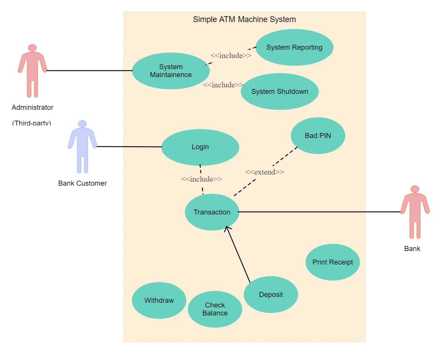
Up to now, you’ve learned about objects, relationships and guidelines that are critical when drawing use case diagrams. I’ll explain the various processes using a banking system as an example.
Actors are external entities that interact with your system. It can be a person, another system or an organization. In a banking system, the most obvious actor is the customer. Other actors can be bank employee or cashier depending on the role you’re trying to show in the use case.
An example of an external organization can be the tax authority or the central bank. The loan processor is a good example of an external system associated as an actor.
Now it’s time to identify the use cases. A good way to do this is to identify what the actors need from the system. In a banking system, a customer will need to open accounts, deposit and withdraw funds, request check books and similar functions. So all of these can be considered as use cases.
Top level use cases should always provide a complete function required by an actor. You can extend or include use cases depending on the complexity of the system.
Once you identify the actors and the top level use case you have a basic idea of the system. Now you can fine tune it and add extra layers of detail to it.
Look for common functionality that can be reused across the system. If you find two or more use cases that share common functionality you can extract the common functions and add it to a separate use case. Then you can connect it via the include relationship to show that it’s always called when the original use case is executed. ( see the diagram for an example ).
There may be instances where actors are associated with similar use cases while triggering a few use cases unique only to them. In such instances, you can generalize the actor to show the inheritance of functions. You can do a similar thing for use case as well.
One of the best examples of this is “Make Payment” use case in a payment system. You can further generalize it to “Pay by Credit Card”, “Pay by Cash”, “Pay by Check” etc. All of them have the attributes and the functionality of payment with special scenarios unique to them.
There are some functions that are triggered optionally. In such cases, you can use the extend relationship and attach an extension rule to it. In the below banking system example “Calculate Bonus” is optional and only triggers when a certain condition is matched.
Extend doesn’t always mean it’s optional. Sometimes the use case connected by extending can supplement the base use case. The thing to remember is that the base use case should be able to perform a function on its own even if the extending use case is not called.
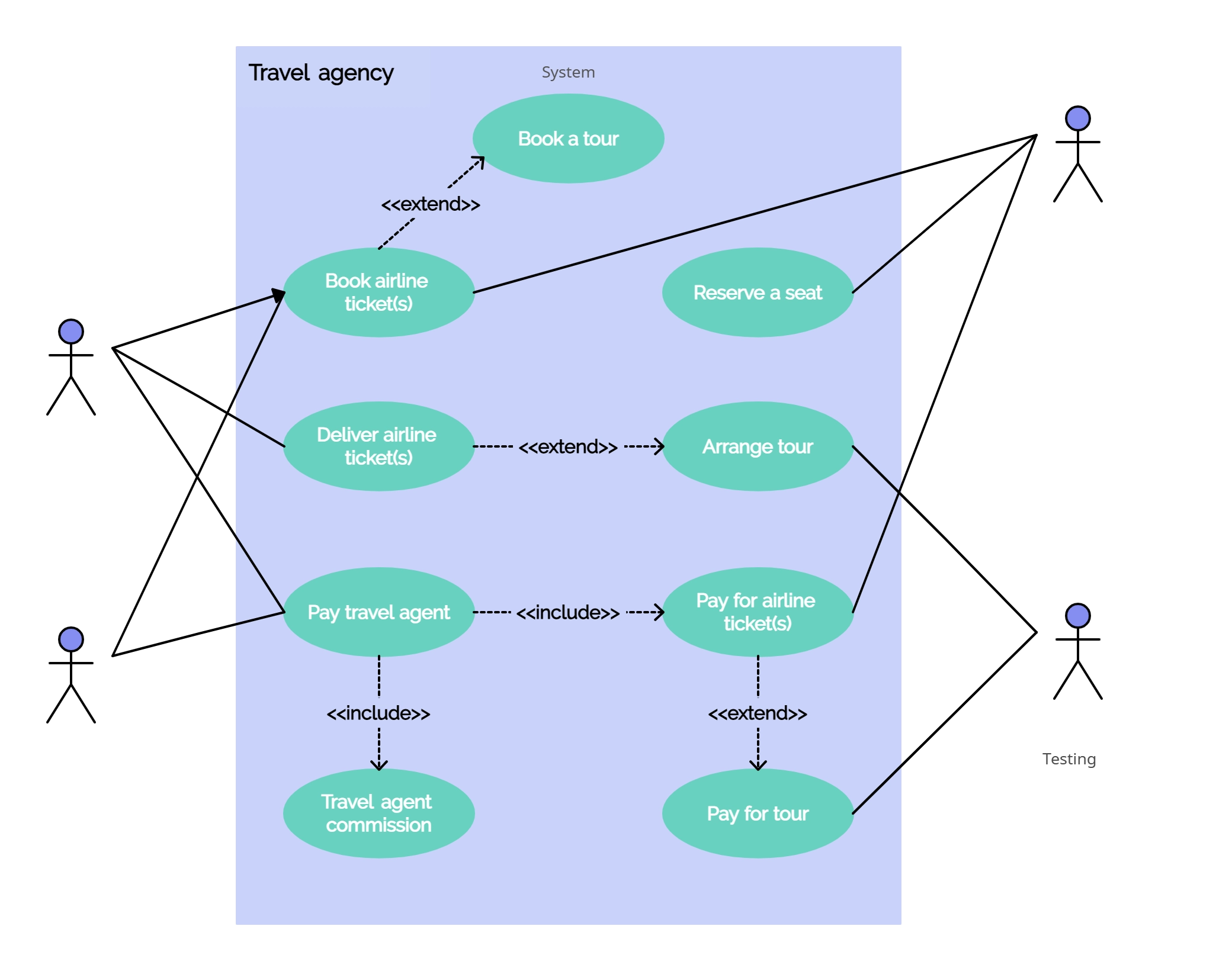
We’ve gone ahead and created use case diagram templates for some common scenarios. Although your problem or scenario won’t be exactly like this you can use them as a starting point. Check out our use case diagram templates.
We’ve tried to comprehensively cover everything you need to know about creating use case diagrams. If you have doubts about any section or can think of ways to improve this tutorial please let us know in the comments.
Join over thousands of organizations that use Creately to brainstorm, plan, analyze, and execute their projects successfully.
In a use case diagram, the following elements are typically included:
On the other hand, use case diagrams do not include the following:
Software engineer turned tech evangelist. I handle marketing stuff here at Creately including writing blog posts and handling social media accounts. In my spare time, I love to read and travel.